- Home
- Product Center
- Integrated Switch Mo…
- Optical Line Protect…
- Optical Line Protect…
Optical Line Protection Module
Optical Line Protection Module
Product description
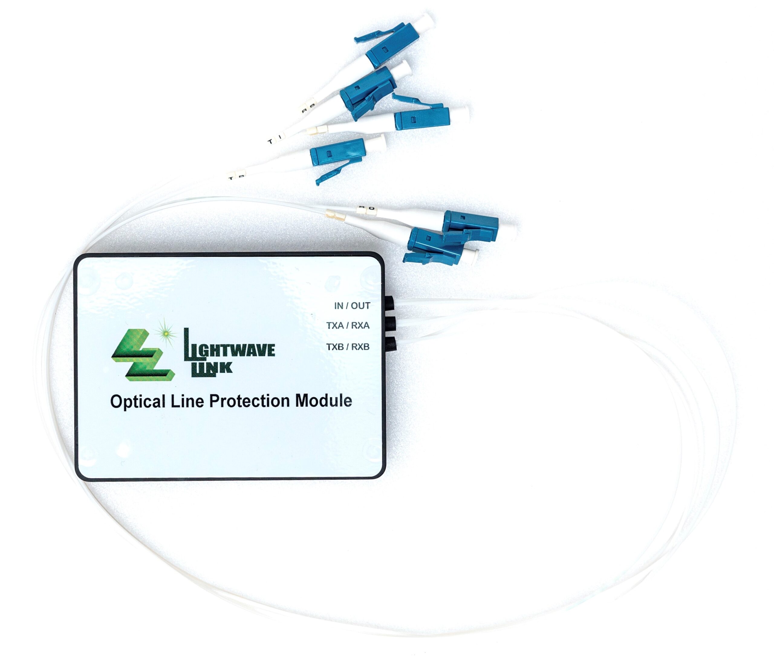
Lightwave Link Inc OLPM (Optical Line Protection Module) is combined with optical switch, optical splitter and optical power monitoring function.
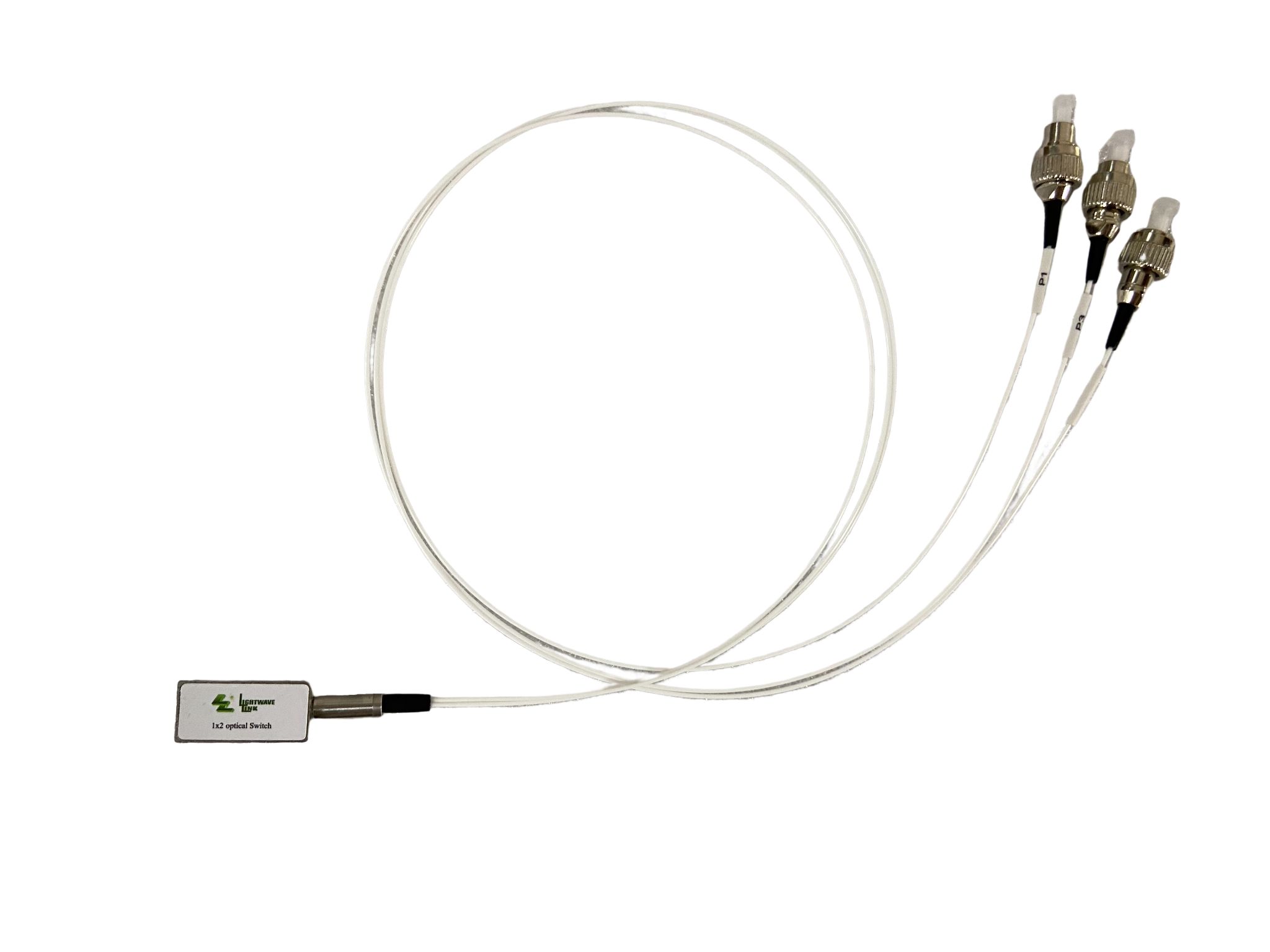
The OLPM is consisted of one 1×2 optical switch, one 1×2 optical splitter and PD monitoring. The subsidiary electrical circuitries are for driving optical switch, performing PD monitoring and demarcating PD linear range with I2C interface.
The main function of OLPM are splitting optical signals, selecting optical light path and monitoring the optical power.
Lightwave Link Inc OLPM complies with TELCORDIA GR-1312-CORE.
Key features
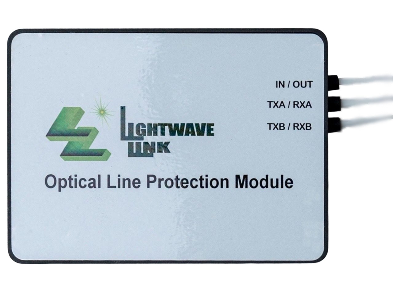
.Input port (IN) light signal output to TXA and TXB via 50/50 splitter.
.Light signal is from RXA to Tap1, 2.5% for optical power monitoring and 97.5% for transmission to 1×2 optical switch.
.Light signal is from RXB to Tap2, 2.5% for optical power monitoring and 97.5% for transmission to 1×2 optical switch.
.Output port (OUT) will output the light signal from RXA and RXB via selected optical path by 1×2 optical switch.
.The PD monitor results (analog signals) will convert to digital signals by AD convertor and output to management system via I2C interface.
.There are optical switch driving circuitry inside and control the optical switch’s status via electrical pin and timing signals.
.There is EEPROM with I2C interface to keep two demarcated PDs’ linear ranges.
.There is online function inside for status judgment from management system.
.There are 40 optical power data in EEPROM, the optical power of AD monitoring will compare with EEPROM and find the optical power range then upload to management system.
Application areas
.Split the input light source to two paths by 1×2 splitter (INTXA/TXB).
.Monitoring the optical powers from RXA/RXB and feedback to management system via I2C interface. Management system will control the optical switch via subsidiary circuitries to obtain the optical light path selecting function.
Product characteristics
| Parameter | Symbol | Min. | Typ. | Max. | Unit | |
| Application wavelength | 1260~1360 / 1490~1640 | nm | ||||
| Optical Power Detect Range | λop | 1528~1565 | nm | |||
| Tap Coupler Ratio | 2.5 | % | ||||
| Input Power Range | IN | P | ≤500 | mW | ||
| RXA or RXB | -30 | +10 | dBm | |||
| Optical Power Detect Precision | ±0.5dBm @ 0 dBm≤P≤+10 dBm | dB | ||||
| ±0.6dBm @ -20dBm≤P<0 dBm | ||||||
| ±0.8dBm @ -30dBm≤P<-20dBm | ||||||
| Insertion Loss 1 | IN ⇔ TXA &TXB | IL | 4.5 | dB | ||
| RXA or RXB ⇔OUT | 1.6 | |||||
| Polarization Dependent Loss | PDL | ≤0.3 | dB | |||
| Directivity | DIR | ≤-50 | dB | |||
| Cross Talk | CT | ≤-55 | dB | |||
| Polarization Mode Dispersion | PMD | ≤0.2 | Ps | |||
| Return Loss 1 | RL | ≤-40 | dB | |||
| Operation Temperature | Top | -10 | 70 | ℃ | ||
| Storage Temperature | Tstg | -40 | 85 | ℃ | ||
| Operation Humidity | Hop | 5 | 95 | %RH | ||
| Storage Humidity | Hstg | 5 | 95 | %RH | ||
| Dimension (H x W x L) | 13.5 x 75 x 55 | mm3 | ||||
| Weight 2 | 70 | g | ||||
1. With connectors.
2. The product weight exclude optical connectors.

