- Home
- Product Center
- Optical Bypass Modul…
- 100G
- 100G Dual Port Singl…
100G Dual Port Single Mode
100G Dual Port Single Mode
Product description
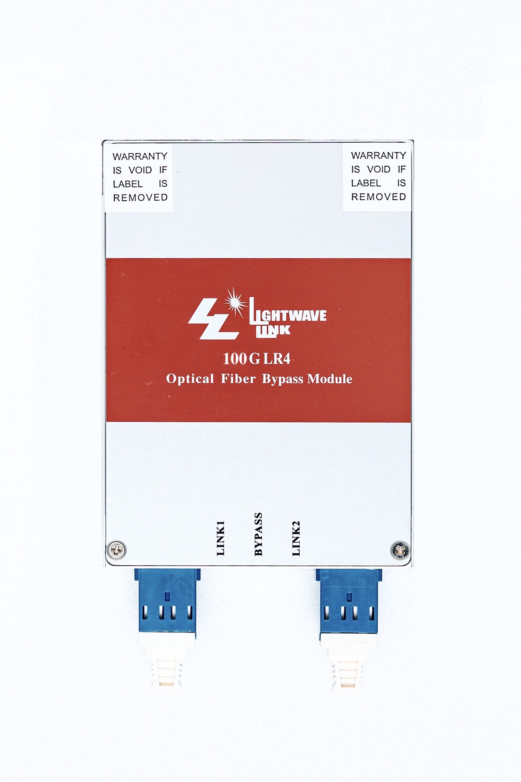
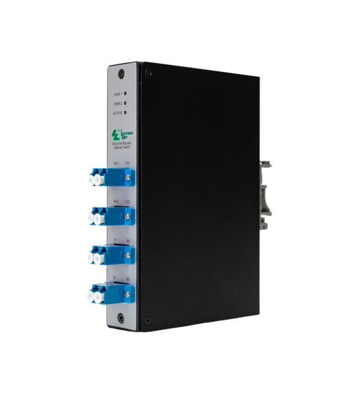
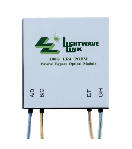
The 1310nm 100G Dual QSFP+ LR4 quad port bypass module is designed as alternative 100Gbps dual QSPF+ LR4 transceiver. Its innovated design able the fiber bypass function become selectable within single PCI card. The 1310nm 100G Dual QSFP+ LR4 quad port bypass module is design expressly for Intrusion Prevention System (IPS) provides complete visibility to network traffic, It also introduces a point of failure should the IPS lose power, cable fail or application freeze.
This interconnecting system include dual ways transceivers offers 4 channels and maximum bandwidth of 100Gbps. It integrates four data lanes in each direction with 100 Gbps aggregate bandwidth. Each lane can operate at 103.1 Gbps up to 10Km using Single Mode fiber(SMF). The optical interface uses a Dual-LC connector.
Key features
.Compliant with 100G Ethernet
.IEEE 802.3ba 100GBASE-LR4 standards
.Compliant with SFF-8436 QSFP+ specification Revision 3.5
.Unretimed XLPPI electrical interface
.Utilizes a standard optical fiber with Dual-LC optical connector
.Link up to 10Km using Single Mode Fiber (SMF).
.Laser Class 1 Product with comply with Requirements of IEC 60825-1 and IEC 60825-2
Application areas
.Client-side 100G Telecom connectionss
.STTA/SAS Storage
.In-Line Sercurity
.Web Acceleration Apliances
Product characteristics
| Parameter | Symbol | Min. | Typ. | Max. | Unit | Note |
|
Transmitter |
||||||
| Lane center Wavelengths(range) | λC | 1294.53-1296.59
1299.02-1301.09 1303.54-1305.63 1308.09-1310.19 |
nm | |||
| Total Average Launch Power | Pout | 10.5 | dBm | |||
| Average Launch Power, each lane | TXPx | -4.3 | 4.5 | dBm | 1,6 | |
| Optical Extinction Ratio | ER | 4 | dB | |||
| Output Optical Modulation Amplitude,per lane | TxOMA | -1.3 | 4.5 | dBm | 1 | |
| Difference in Power between any Two Lanes in OMA | 5 | dB | 1 | |||
| Transmitter and Dispersion Penalty,each lane | TDP | -2.3 | 2.2 | dBm | ||
| Relative Intensity Noise | RIN | -130 | dB/Hz | 7 | ||
| Disable Output Optical Power | PO-OFF | -30 | dB | |||
| Sidemode Suppression Ratio | SSRmin | 30 | dB | |||
| Optical Return Loss Tolerance | 20 | dB | ||||
| Transmitter Reflectance | Rt | -12 | dB | |||
| Eye Mask Coordinate:
X1, X2, X3; Y1, Y2, Y3 |
Specification Value:
0.25, 0.4, 0.45; 0.25, 0.28, 0.4 |
UI | 2 | |||
|
Receiver |
||||||
| Center Wavelength, each lane | λC | 1294.53-1296.59
1299.02-1301.09 1303.54-1305.63 1308.09-1310.19 |
nm | |||
| Damage threshold | 3.4 | dBm | ||||
| Average Receiver Power, each lane | Pin | -10.6 | 4.5 | dBm | 3,8 | |
| Stressed Sensitivity (OMA) | -6.8 | dBm | 3 | |||
| Receiver Sensitivity (OMA),each lane | -8.6 | dBm | ||||
| LOS Assert | PA | -24 | -13.6 | dBm | ||
| LOS De-Assert | PD | -11.6 | dBm | |||
| LOS Hysteresis | 1.5 | dB | ||||
| Total Average Receiver Power | Pin | 8.3 | dBm | |||
| Receiver Power (OMA) per Lane | 4.5 | dBm | ||||
| Return Loss | -26 | dB | ||||
| Vertical eye closure penalty, per lane | 1.9 | dB | ||||
| Receive electrical 3 dB upper cutoff frequency, per lane | 31 | GHz | ||||
|
Optical Bypass Switch |
||||||
| Center Wavelength | λC | 1260 | 1335 | nm | ||
| Insertion Loss (Normal Mode) | IRL | -4.0 | 0 | dB | 4 | |
| Insertion Loss (Bypass Mode) | IRL | -4.0 | 0 | dB | 5 | |
| Return Loss (Bypass Mode) | ORL | 50 | dB | |||
1. Output power is power couples into a 9/125um Single-mode fiber (SMF).
2. Hit ratio= 5×10E-5 per sample.
3. Measured with 25.78125Gbps of PRBS-31 at 10-12 BER.
4. Normal Mode (Bypass Mode Off).
5. Bypass Mode (Normal Mode Off).
6. Minimum value is informative.
7. RIN is scaled by 10*log(10/4) to maintain SNR outside of transmitter.
8. Minimum value is informative, equals min TxOMA with infinite ER and max channel insertion loss.
