- Home
- Product Center
- Optical Bypass Modul…
- 40G
- 40G Dual Port Multi …
40G Dual Port Multi Mode
40G Dual Port Multi Mode
Product description
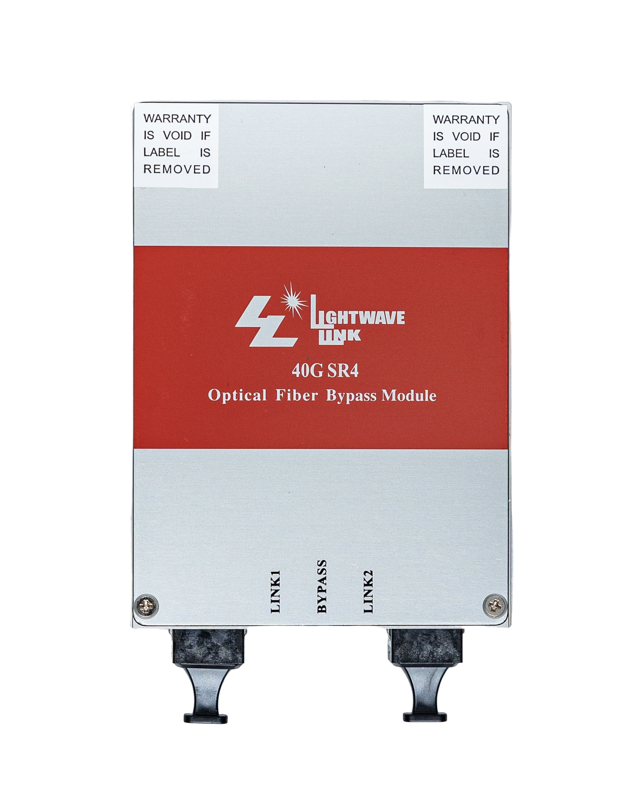
The 850nm 40G Dual QSFP+ SR4 quad port bypass module is designed as alternative 40Gbps dual QSPF+ SR4 transceiver. Its innovated design able the fiber bypass function become selectable within single PCI card. The 850nm 40G Dual QSFP+ SR4 quad port bypass module is design expressly for Intrusion Prevention System (IPS) provides complete visibility to network traffic, It also introduces a point of failure should the IPS lose power, cable fail or application freeze.
This interconnecting system include dual ways transceivers offers 4 channels and maximum bandwidth of 40Gbps. It integrates four data lanes in each direction with 40 Gbps aggregate bandwidth. Each lane can operate at 10.3125 Gbps up to 100 m using OM3 fiber or 150 m using OM4 fiber. The optical interface uses a 12/8-fiber MTP® (MPO) connector.
Key features
.Compliant with 40G Ethernet
.IEEE 802.3ba 40GBASE-SR4 standards
.Compliant with SFF-8436 QSFP+ specification Revision 3.5
.Unretimed XLPPI electrical interface
.Utilizes a standard 12/8 line optical fiber with MP-MTP optical connector
.Link up to 100m using OM3 MMF
.Laser Class 1 Product with comply with Requirements of IEC 60825-1 and IEC 60825-2
Application areas
.40GbE and 40G-IB-QDR / 20G-IB-DDR / 10G-IB-SDR interconnects
.Client-side 40G Telecom connectionss
.4G/8G/10G fiber Channel
.STTA/SAS Storage
.In-Line Sercurity
.Web Acceleration Apliances
Product characteristics
| Parameter | Symbol | Min. | Typ. | Max. | Unit | Note |
|
Transmitter |
||||||
| Center Wavelength, each lane | λC | 840 | 860 | nm | ||
| Spectral Width – RMS | Δλ | 0.65 | nm | |||
| Average Output Optical Power, each lane | Po | -7.6 | 2.4 | dBm | 1 | |
| Optical Extinction Ratio | ER | 3.0 | dB | |||
| Output Optical Modulation Amplitude,
per lane |
OMA | -5.6 | 3.0 | dBm | 1 | |
| Difference in Power between any Two Lanes in OMA | 4.0 | dB | 1 | |||
| Transmitter and Dispersion Penalty,
each lane |
TDP | 3.5 | dB | |||
| Relative Intensity Noise | RIN | -128 | dB/Hz | |||
| Disable Output Optical Power | PO-OFF | -30 | dB | |||
| Optical Return Loss Tolerance | 12 | dB | ||||
| Eye Mask Coordinate:
X1, X2, X3; Y1, Y2, Y3 |
Specification Value:
0.25, 0.4, 0.45; 0.25, 0.28, 0.4 |
UI | 2 | |||
|
Receiver |
||||||
| Center Wavelength, each lane | λC | 840 | 850 | 860 | nm | |
| Damage threshold | 3.4 | dBm | ||||
| Average Receiver Power, each lane | Pin | -11.0 | 2.4 | dBm | 3 | |
| Stressed Sen
itivity (OMA) |
-5.4 | dBm | 3 | |||
| Receiver Reflectance | -12 | dBm | ||||
| LOS Assert | PA | -30 | dBm | |||
| LOS De-Assert | PD | -7.5 | dBm | |||
| LOS Hysteresis | PA-PD | 0.5 | 1 | 3.0 | dB | |
|
Optical Bypass Switch |
||||||
| Center Wavelength | λC | 670 | 850 | 980 | nm | |
| Insertion Loss (Normal Mode) | IR | -4.0 | 0 | dB | 4 | |
| Insertion Los
(Bypass Mode) |
IRL | -4.0 | 0 | dB | 5 | |
| Return Loss (Bypass Mode) | ORL | 30 | dB | |||
1. Output power is power couples into a OM3 50/125um Multi-mode fiber (MMF).
2. Hit ratio= 5×10E-5 per sample.
3. Measured with 10.3125Gbps of PRBS-31 at 10-12 BER.
4. Normal Mode (Bypass Mode Off).
5. Bypass Mode (Normal Mode Off).
